Moggie
Her Engine and Gearbox Transplant
|
The Hendersons Moggie's engine transplant |
|
Moggie Her Engine and Gearbox Transplant |
|
Having acquired the engine and gearbox, I sought experience and professional help. I had information and advice from John Burks who had been there and done that in a much earlier Morgan. Thanks John! I also lined up professional help with motor mounts, prop shaft, exhaust system, plumbing and electrical systems. I had neither the expertise nor the equipment to handle these things.
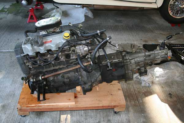
Although I had purchased the engine in December of 2006, I didn’t start the conversion until February of 2007. The Christmas holidays and a trip south caused the delay. I pulled the original engine and gearbox at home and put them in a corner of my garage. I also removed the gearbox cover, the prop shaft cover, the prop shaft and the seats. At that time the odometer showed 50,175 miles on Moggie.
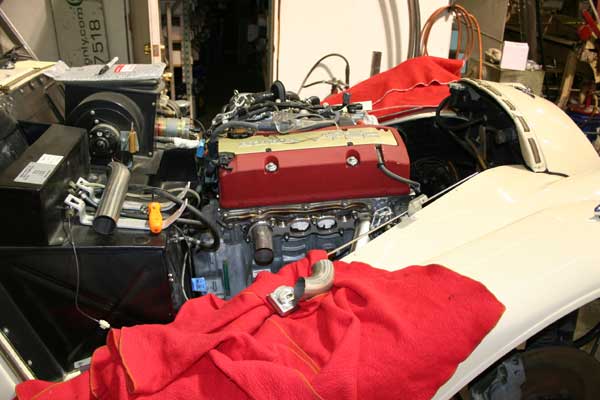
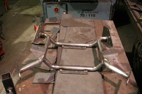
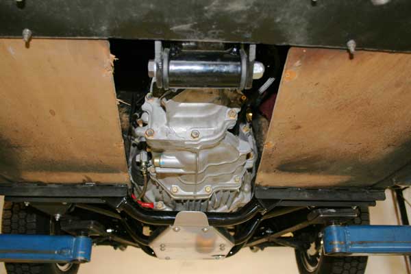
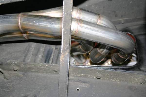
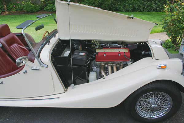
Finally the day arrived for the Mog to be moved to the shop where the S2000 engine and gearbox would be installed. We loaded her onto a ramp truck and away she went. It was a Friday and late in the afternoon, so work was set to begin on Monday. The basic installation was to be done at Chris Hoover Enterprises. Chris separated the engine and gearbox, removed the exhaust system and a few other items. He found that the Honda gearbox is wider than the Ford, so he did some surgery on the firewall. Then we lowered the engine in and reconnected it to the gearbox just enough to see how things lined up. At this point Chris could determine how to construct the motor mounts and the rear gearbox mount. At one point Chris had thought of routing the exhaust system under the engine and out the driver’s side. We could now see that it would pass too close to the master cylinder, so the decision was made to go out the passenger’s side. The Honda headers were going to be too difficult to alter for this route, so Chris ordered the parts to build stainless headers and collectors from scratch. I purchased a plug-compatible and fully programmable ECU from AEM. I also replaced the mechanical speedometer and tachometer with new electronic units from VDO. Their Vision series look like the originals except that the needles are red. As Mel and I left for Africa for five weeks Chris was looking at a week or two to finish his part of the project and flatbed the car to Mark Larsen’s Import Auto Center. Mark had done the maintenance on our cars for many years and had a mechanic who was a Honda wiz and had done a lot of custom stuff as well. I had ordered the ECU to be shipped to Mark. I hoped that by the time we got back home on April 10th a lot of the plumbing and electrical would be done and we would be close to having her back on the road. When we got home I called Chris. He answered his cell phone in Las Vegas. I finally saw him on April 16th and he had hardly touched the car while we were gone. I did everything I could think of to keep him working on my car rather than other projects. He finally got tired of me bugging him and started really hitting it to get rid of me. The position of the Honda motor mounts would put them over weak areas of the chassis, so Chris designed and fabricated a mounting system to compensate. It consists of steel plates and tubular members as shown below. The engine could then be lowered onto the mounts and the rear mount for the gearbox could be done.
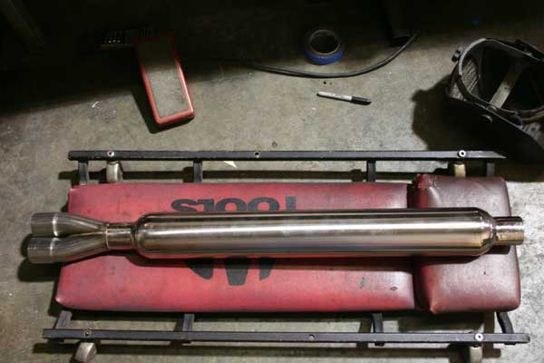
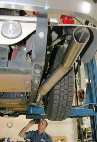
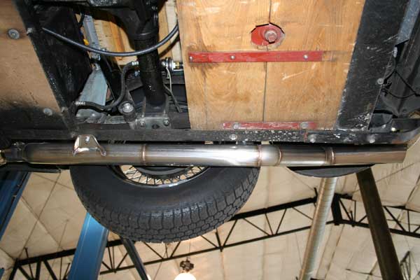
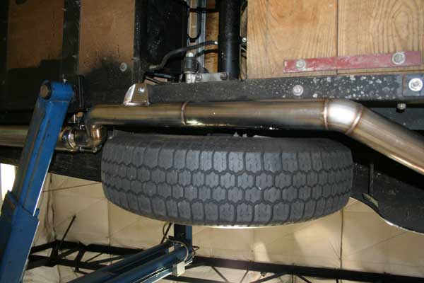
I wanted the exhaust to be reasonably quiet without sacrificing too much performance, so I ordered a muffler from Never Rust in Pittsburgh. It is 4" round with internal baffles and is all stainless steel. It is shown below with the two into one fitting welded to it. By this time the headers had been fabricated.
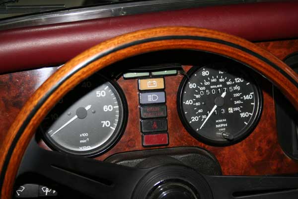
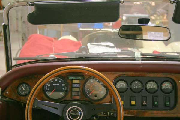
I set the new tach and speedo into the dash to see how they would look with the smaller original instruments. The originals have beveled bezels and white pointers. The new instruments have flat bezels and red pointers. Still, they look okay together.
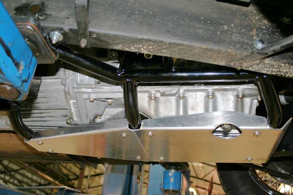
The engine was removed to permit cleanup work on the firewall and inner valance and removal of the motor mount for powder coating. The motor mount can be seen more easily below. The plates at the front bolt to the chassis where the original Ford mounts did. The plates at the back bolt to triangular plates that, in turn, bolt to the chassis where it meets the firewall. The cross members provide additional rigidity, as well as mounting points for the skid plates. Since the crank case is cast aluminum, it seemed advisable to provide some protection.
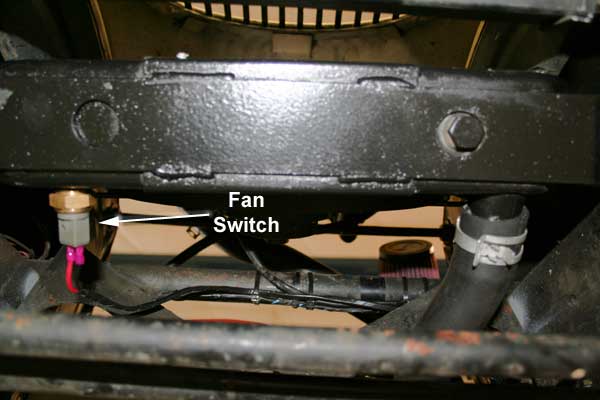
I had told Chris to forget about the gearbox and prop shaft tunnels (I had located someone else to do them) and concentrate on those things he had to do to get Moggie ready for the plumbing and electrical work. To his credit, he stuck with it and the end was in sight. It had been frustrating and had taken way too long and had required way too much of my time standing over him. However, I do have to admit that he did beautiful work, and his solutions to various problems were well thought out and executed. At long last we rolled the Mog out of his shop on May 22nd and transported it to Mark’s shop. The wizard in Mark's shop is Bill Duncan - a factory trained Honda technician. He first tackled the coolant plumbing and found that the stock S2000 radiator hoses would fit with a few modifications. The lower hose must be cut a little shorter. For the upper hose to fit we removed the radiator and took it to a shop to have the top pipe replaced with one a little longer and at 45 degrees. We also had the shop solder a bung into the bottom tank to accept a stock Honda fan switch. Bill found a hose that looked like it was made specifically to connect the return line from the heater to the block. He mounted the original shutoff valve that controls flow to the heater and connected it to the block and the heater. He also found an appropriate place to drill and tap a hole for the temperature gauge sender. We used the original sender so the original gauge could be retained. With coolant issues resolved, Bill turned to brake lines. Since the exhaust system switched sides, the brake lines would have to do the same. The brake pressure switch was mounted to the left inner valance and front lines went through it from the master cylinder. The rear brake line went from the master cylinder through the chassis (as it had done on the other side) and along the chassis rail to the rear. There it went back through the chassis and up to a steel tubular piece that crosses the back of the car above the drive shaft and battery. It followed that piece to the right side of the car, where it went back down and connected to the original flexible line. In this way it was protected and the lines that connect to the rear wheel cylinders could be left as they were. The brake lines were secured with line clamps with rubber grommets and with pop rivets. While the car was in the air I took the opportunity to take a few photos.
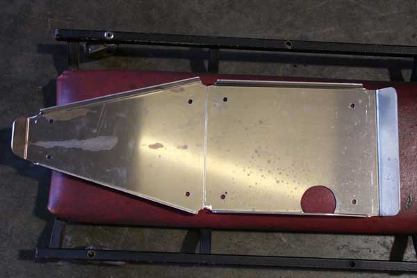
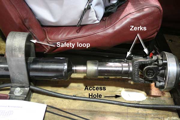
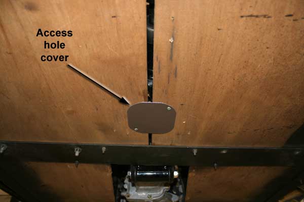
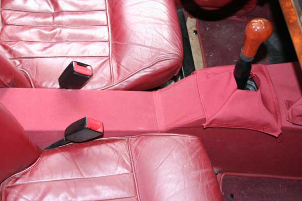
Fuel lines were next. We used a Honda fuel filter and installed an MSD 2225 in-line fuel pump back near the tank. The feed and return lines we had installed during the original conversion to petrol were just fine and connected easily to the new pump and filter. I had received a gift certificate for a K&N air filter when I attended MOG 36 the prior year. Mark and I browsed the K&N web site and I ordered a SN-2620 filter. It is a conical shape with a 20 degree angle from the connection to the throttle body. Once installed it looked like it was made for this application. While all this was going on, Mark's cousin, Joe, was making the gear box and drive shaft covers. Joe is a very talented sheet metal man. He first produced a template version using light sheet metal that he could easily trim and shape. When he had that version as we wanted it, he produced the final version out of sheet metal that is heavier than the originals. We opted to avoid bends that were too rounded as they would be much more difficult and therefore more costly. The new covers are flat on top with tight radius edges. Joe also produced a 1/4" steel loop strap that is bolted to the chassis cross member where the seat belts attach. Should the drive line ever let go, that strap will keep the shaft from whipping all over the place and taking out body parts in the process. I still have to come up with some sort of cover for the gearbox tunnel, but that can wait. The leather that was on the original drive shaft cover will fit on the new one. Rather than cut an access hole in the tunnel to get at the zerks on the drive shaft, we opted to cut a hole in the floor boards and produce a simple metal plate that can be attached with screws and cover the hole. The competed tunnels were delivered on June 14th; the same day the plumbing was completed.
All that is left under the hood is installing the clutch reservoir, filling it and bleeding the clutch. The tunnels are being covered. I got a yard of Sunbrella and have covered the prop shaft tunnel. The gearbox tunnel cover pattern has been made and the cover has been cut out. I still have to produce boots for the shift lever and hand brake, and glue the cover in place. Some stitchery will be needed. I'll secure the boots with velcro. It won't be long now.
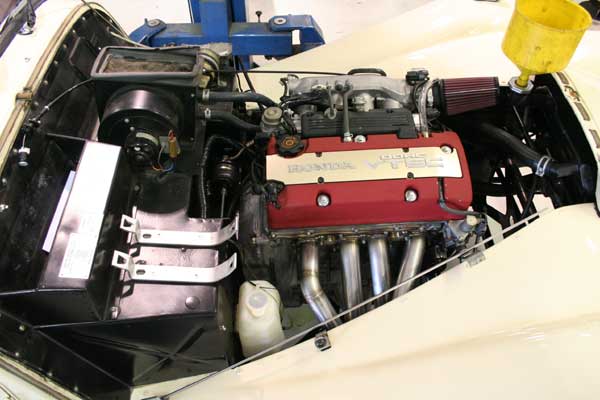
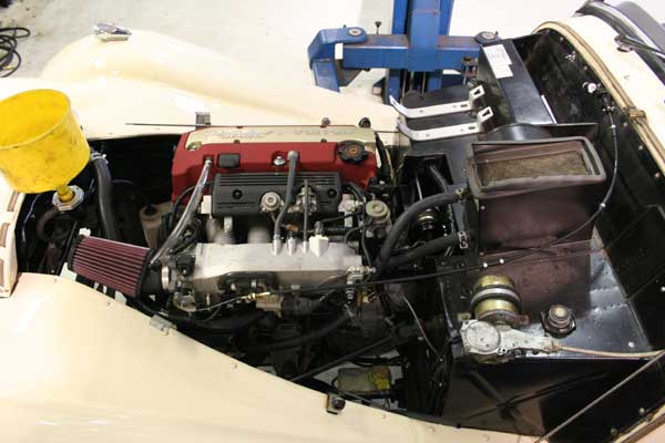
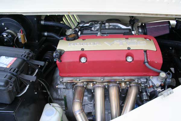
The work is complete and Moggie is on the road as of June 19th. She sounds wonderful and the installation looks great. I took her to an AEM dealer locally and had them fine tune the ECU. Then Wednesday afternoon I filled the tank on the way home. On Thursday we left home for the Devil's Punch Bowl weekend run and drove to Kelso, WA to meet up with a number of other Morgan owners. Friday morning we all took off on a 200 or so mile drive to Newport, OR. Heinz Stromquist had once again plotted a wonderful route over two-lane roads (and one that was so narrow that it didn't have a center line) that meandered up and down hill. The car ran brilliantly and cool as a cucumber. On Saturday morning we refueled In Newport and had averaged 27.25 MPG. Later that day we made our way to the Alpine Chalets where many of the gang were staying. Everyone there took a look at the installation and all agreed that it looked like the engine was made to be there. I could not be happier with the outcome. With Honda reliability it is likely that she will never require anything more than routine oil changes, but if she does, any competent Honda shop in the world could get the parts and handle the work. I don't have a pattern for the bits that it took to pull this together, but I suspect patterns could be made of the engine and gearbox mounts. The headers would probably have to be custom made. I would be happy to help anyone who wanted to follow in her footsteps. |

|