Moggie
Her Propane to Petrol Conversion
|
The Hendersons Moggie's propane to petrol conversion |
|
Moggie Her Propane to Petrol Conversion |
|
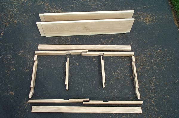
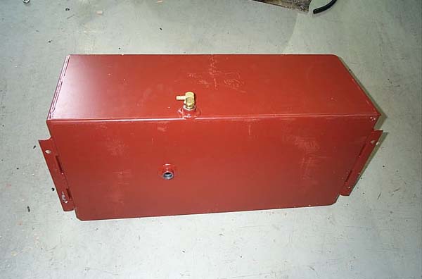
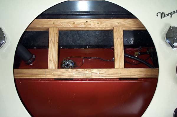
The 'reversion' to petrol turned out to be a major project. The first task was to determine what parts would have been installed on the engine originally. I tried a variety of sources before hitting on the idea of locating someone in the U.K. with a similar car. I used an Internet based registry of Morgan owners and located three who met the criteria. I sent emails to each of them and got a prompt response from one - Mike Schofield in Lytham St. Annes. Mike has a '90 4/4 and was immensely helpful. He sent me a number of photographs, partially disassembling his car to take some of them. He went to the local Ford agent and got a copy of the parts page for the fuel pump. And he sent me a dimensioned drawing of his fuel tank. It turned out that the particular carburetor used on that engine was one only available in Europe. I was able to find a business in England that could supply the carburetor and the fuel pump, so I was in business. The next challenge was the fuel tank. I decided to have one built locally so that I could 'duplicate' Mike's tank. Based on the measurements, it had a capacity of about 17 gallons. I felt it would be wise to ensure that it would fit into our Morgan, so I removed the spare wheel and the panels beneath it to take some measurements. That was when I discovered another major challenge. There is a wooden structure that supports the spare wheel in Morgans as they come from the factory. They have a wooden frame mounted on a steel chassis, so this was no surprise. The surprise was that our car no longer had that structure. It had been removed when the conversion to propane was done. So now I had to figure out how to fabricate a replacement structure that could be mounted in the car with the body on. The factory puts all that part together before mounting the body panels. The good news was that the tank would fit. That would give us wonderful cruising range. I located a local company that could build the fuel tank for me at less than half the cost of ordering one from England. I created detailed plans for the tank from the drawing Mike had sent. I went to a local firm to get the fittings for fuel feed and return. They were able to locate a pressure relief/rollover check valve for me. For the filler neck, I picked up a piece of muffler tail pipe. Part of this pipe was also taken to a fellow who could fit it to the underside of the fuel cap to replace the neck that had been cut off during the propane conversion. With all these things in hand I ordered the tank. Returning to the missing wooden structure, I designed a replacement structure that could be installed with the body on the car and picked up two pieces of Ash – a 1 x 8 x 72” piece that could provide the two boards the fuel tank sits on and a 1 x 6 x 72” piece that could be ripped to 1 ¾” wide pieces to build the spare wheel support frame. I ripped the 1 x 8 to 7 ½” wide, figuring that the extra 1” (the bottom of the tank is 14” wide) could be used as a place to mount the fuel filter. Then I cut it into two pieces 36” long. The original boards were only ½” thick, so I dado’d the ends of the new boards to that thickness to avoid having the fuel tank sit too high. The holes where the boards attach to the frame rails and where the tank attaches to the boards were drilled once the boards were in place. The hole that provides access to the drain plug was cut at that time also. At that point the tank boards were ready to be treated with a wood preservative. I learned that the metal Relief line on the propane tank could be disconnected from the upper spare wheel well body panel with no problem. Once that was done the upper panel could be removed. That made design and measurement of the new support frame pieces much easier. At that point I also removed the bolts holding the propane fill and vent fittings in place. I found that 90° angled pieces of sheet metal had been installed on both sides to make the rear body panel less flexible. They were bolted to the inner fender walls and had holes through which the fuel caps were attached. The one on the left (fill) side was 1/8” thick and the one on the right side was 1/16” thick. I decided to retain them, but notched the corner where one of the horizontal wood frame members would go. I also found that the radio antenna had the cable to the radio along side the mast. The antenna had been installed so that the cable was between the inner fender wall and the mast. I turned the antenna 180° to provide more clearance for the wood frame member that would attach to the inner fender wall. That gave me about 5/8” clearance. I had measured the depth from the rear body panel to the removable panels at 1 3/8”. I could see where the original wood frame side members had attached to the inner fender walls, and determined that the original depth would have been about ¾” greater. I decided to split the difference to ensure that the new frame would clear the top of the tank. As you will see from the following documentary, this was a sort of ‘Rube Goldberg’ project. I was having to devise ways to establish positions and take measurements to try to make the new frame as square as possible. It would not be perfect, but it would be good enough and it would be adequately stout. I measured the angle (crudely) made by the rear body panel and the bumper impact absorber where it attached to the inner fender wall. The plan was to cut that angle on the ends of the side members of the wood frame to maximize the surface for mounting the horizontal frame members. I cut the left side member first and verified that it fit as planned before cutting the right side member. The next step was to determine where to dado the undersides of those members so they would fit flush over the pieces of sheet metal mentioned earlier. I held those pieces of sheet metal in place and scribed a line around their edges on the inner fender wall. Then I held the side members in place and marked the area to dado. I also marked the right side member where it would have to be notched for the radio antenna. There is a piece of wood that is part of the car’s frame and runs across the back at the top of the rear body panel. I measured 3 5/8” down from that piece as the place to position the upper horizontal frame member. The lower member would be mounted as low as possible but it would be higher than the original because of the bumper impact absorbers. That produced a span of about 10” between the inner edges of the upper and lower frame members. The span between the vertical members was dictated by the location of the rain hat for the propane tank. If the rain hat was not reinstalled there would be a large hole in the upper removable body panel. That span was 11”. That yielded an outer span of 14 ½”. The ¼” aluminum plate that supports the removable body panels is 16” wide. It was to be mounted to the vertical frame members with 4 countersunk flat-head bolts. Before removing the propane tank I reattached the aluminum plate and measured the placement of the holes where the wheel support is attached. After the new frame was installed, the aluminum plate was positioned and the holes drilled to attach it to the new frame. Upper bolt holes in the side members were the next order of business. I was able to use an existing 3/8” hole on the left, but had to drill a new hole on the right. To get the side members properly positioned I cut a 10” long by 2 3/8” wide piece of wood. This piece was placed against the inner fender wall and up against the under side of the rear body panel. The side member was then snugged up against this piece and downward against the bumper impact absorber. This ensured that the depth was uniform top to bottom and on both sides. Once the side members were drilled, I secured them with bolts so that I could mark the ‘precise’ location of the upper horizontal member. I had a piece of wood that would just rest on both side members and could just be inserted beneath the rear body panel. I taped a small piece of cardboard to the left side member at the top of the planned cut for the horizontal member. I then held the horizontal test piece up against that cardboard and measured down from the piece of frame mentioned two paragraphs up. When I was satisfied that the test piece was properly positioned I marked the edge of the right side member with an Exacto knife. A pencil mark would not have been sufficiently accurate. The side pieces were then removed and I marked the edge of the left member with the knife. I then measured down from the knife cuts to mark the position of the bottom horizontal member. That, in turn, gave me the length of the vertical members. I cut the notches in the side members and sanded them to fit the horizontal members into the notches. It was a lot of detail work, but it paid. With the side members done I turned my attention to the horizontal members. I first dado’d the inner ends to a width of 2”. Then I took them to the car and measured the dimension by which they failed to mate. Dividing this dimension in half (one half for each side), I trimmed the outer ends and rechecked them in the car. After sanding the surfaces of the dado cuts I marked the positions of the vertical members. I made the dado cuts for them and sanded the surfaces of the cuts. I then rechecked the length of the vertical members (the distance between the extremes of the notches in the side members). I cut the vertical members and made the dado cuts at the ends and sanded them. The frame was done. I still had to treat the pieces with wood preservative. I had to drill holes and glue and screw the pieces together, but that had to wait until the propane tank was out. The first task was to put the side members back in place with their top bolts. I was able to drill the holes for the bottom bolts and start assembling and installing the frame. It was very gratifying that it had come together just as I had envisioned it. I had to be able to properly position the aluminum plate, so I reattached it to the propane tank with the two large bottom bolts. I then measured the distance between the center of the bottom bolt hole where the spare wheel support bracket is attached and the inner fender walls. It was 18 5/8” to both sides. I measured the top bolt hole and was surprised to find 18 27/32” to the left and 18 13/32” to the right. I mounted the spare wheel bracket and the spare and took a look. Sure enough, the spare is closer by just a bit to the right side of the round opening in the rear body panel. As I sat sipping a glass of wine and reflecting on the day’s work I had an idea for positioning the aluminum plate. I took two slim pieces of wood cut to 24” long and measured 18 5/8” from one end. I marked that point and drilled holes the size of the bolts that attach the spare wheel bracket. I was then able to position the plate laterally with ease. From there it was a snap to position it vertically before clamping it to the frame and drilling the mounting holes. All woodpieces were cut out of 1” Ash that had an actual thickness of 13/16”. The tank boards were 35 5/8” long. The ends were dado’d to ½” thick, which was the thickness of the original factory boards. The dado cuts were 1 11/16” in from the ends, which left 32 ½” of full thickness that sat between the frame rails. The spare wheel support frame had two extra pieces that ran horizontally and were glued and screwed to the under sides of the main horizontal members. Those pieces were 35 ½” long. The main horizontal members were 19 5/8” long and had dado cuts half their thickness and two inches wide to allow them to overlap in the center. There were also dado cuts half their thickness and 1 ¾” wide to accommodate the vertical members. Those cuts were 11” apart, which produced a distance between the outer edges of the vertical members of 14 ½”. The vertical members were 11 ¾” long and had dado cuts half their thickness and 1 ¾” long at each end. The side members were 15 7/8” long on the top edge and 11 7/8” long on the bottom. They were notched to allow the horizontal members to fit flush with their upper edges. The notches were cut such that the distance between their outer edges was 11 ¾”. That put them as close to the full width part of the member as possible. Screw holes were pre-drilled and countersunk for the flat-head brass wood screws. There were two holes at each point where a horizontal member mounted to a side member. There were also two holes where the left and right horizontal member overlapped. There was one hole where each end of the vertical members notched into the horizontal members. There was an additional hole 4” inboard from each of the vertical member holes. That made a total of eight holes that had 1 ½” screws that went through the horizontal members into the extra pieces that were meant to reinforce the structure. The notch in the inside of the right side member was for the radio antenna.
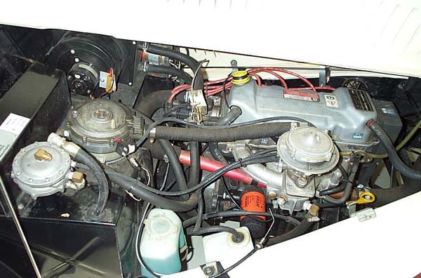
I got started early on removing the propane hardware. The first step was to shut the valve to the line that feeds the propane carb. Then I loosened the fuel line at the valve. There was an escape of pressurized propane for a few seconds. Then I disconnected the fuel line from the valve.
From there it was a simple matter to remove the propane hardware from the engine compartment. The next step was to remove the propane tank. Remove all eight bolts that secure the tank to the steel plates and the plates to the chassis rails and the tank just rotates forward and down. It was rather heavy, so it helped to have a jack under it. The fuel line was then removed by pulling the upholstery away from the passenger side and disconnecting the clamps.
The left side member of the spare wheel support frame had to be in place before the fuel cap with filler neck was installed. It seemed as if the best way to deal with that was to glue and screw the horizontal members to both side members early. Once the propane tank was removed I put the side member/horizontal member assemblies in place and temporarily screwed them together. Then I drilled the lower holes through the side members, the sheet metal and the inner fender walls. I double checked the point 3 ½” forward of the rear chassis cross member. This would be the rearmost point of the top of the fuel tank. I measured up from that point 11 ½” to verify that the spare frame would clear the top of the tank. Then I completed assembly of the spare frame. In the afternoon I picked up the tank. It was rather heavier than I had expected, because they built it from 12 gauge steel rather than 14 gauge. It is much beefier than a stock tank. We found that the tank boards could not be moved into place as is, so we cut 45 degree angles off of opposite corners of the dado’d part of the boards. That did the trick. There was no way to get the tank in place with a board already in, so we lifted the tank up and held it high enough to move the boards in under it. I had measured the spot where the hole would be needed for access to the drain plug. Unfortunately, I didn’t have a jig saw handy, so the hole is rather rough. What the hell, nobody looks under your car anyway. We had to position the tank on the boards and mark all hole locations, then take everything back out to drill the holes in the boards.
The bolts that secure the boards to the chassis and the tank to the boards were put in from the bottom up. This way there was minimum area to be buggered up by running over anything. I figured out that if I slid the tank as far to one side as possible, I could just barely get my hand in to put washers and nuts on the bolts that secure the boards to the chassis. Once that was done I repositioned the tank and secured it. Being rather slim really helped, as there is very little space along side the tank. Finally, I marked and drilled the pilot holes and secured the additional straps to the bottom of the tank boards. The tank was in and everything fit, albeit rather snugly.
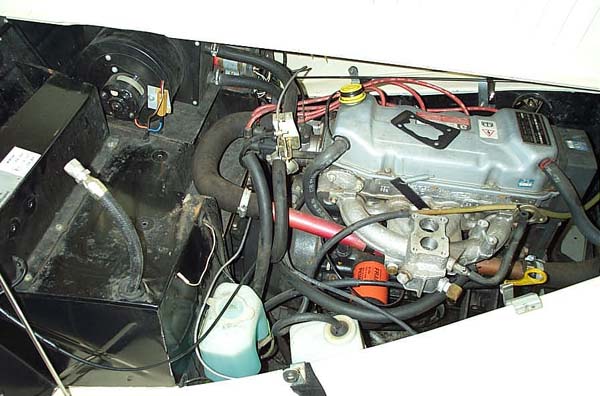
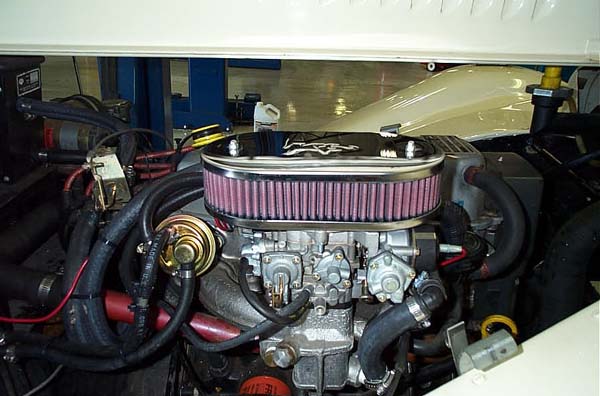
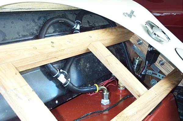
I had earlier put the wooden frame in place and glued and screwed it together. You can only get so far out from center to put screws into the frame from above. I drilled two additional holes from below as far outboard as possible and put screws in the bottom horizontal member. The frame is very stout and should easily support the spare. The bottom horizontal member, with its extra board on the underside, almost rests on the tank. We took two strips of neoprene and sprayed them with adhesive and put them between the tank and the frame. This would help prevent squeaks. As we went through all this we took time to test the fuel tank sender unit. The fuel gauge didn't register. As I looked at the dash it was obvious that a different fuel gauge was installed during the propane conversion. It looked like the other gauges until you noticed that the bezel that secures it was much wider than the others. I sent an email to see if I could get a replacement gauge. Bill, the guy who has the expertise I lack, installed the fuel lines. We put in solid steel lines from the tank to the fuel pump, connected by short rubber hoses and clamps. The steel lines run inside the passenger area, just as the propane line did. They were tucked under the upholstery on the passenger’s side. We restapled and reglued the upholstery. We had to remove the passenger’s seat to install the fuel lines. I had cut the tank boards 1” wider than the bottom of the tank. We mounted the fuel filter atop that 1” space. The clamp that holds the fuel filter and the clamp that holds the fuel line in place are screwed into the leading edge of the tank board. New holes were cut in the firewall and the fuel lines pass through those holes (and grommets). The fuel lines were secured with clamps as appropriate and were positioned so that they wouldn’t suffer any interference from the suspension. Where wood was available we used screws on the clamps. In other places the clamps were pop riveted. Bill is enough of a perfectionist that the whole thing looked very professional. The fuel pump and carburetor were then installed and plumbed. One of the heater sized hoses came forward and was held in place under the choke. It then angled down and connected to the fitting in the intake manifold. There were also electrical wires to the two connections on the carburetor that control the choke and idle. Those were strap tied to the section of heater hose mentioned. There was an in-line fuse in those wires. The original PCV system was retained. A hole was drilled in the bottom of the air filter housing to provide a source of clean air for that system.
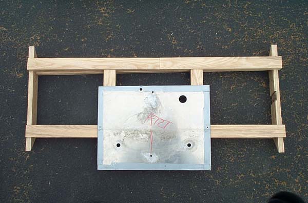
Meanwhile, as Bill was working on the ‘innards’, I was positioning the aluminum plate and drilling it to secure it to the new wooden frame. I had previously measured the distances from the centers of the spare wheel bracket holes to the inner fender walls and to the top and bottom of the circular opening in the rear body panel. I held the plate in place with C clamps just loose enough that it could be moved until it was properly aligned. It was secured to the bottom horizontal frame member with wood screws and to the vertical members with flat head bolts and nuts. The screws and bolts were countersunk to permit the removable panels to sit flush to the aluminum plate. All the heater hose and the three radiator hoses were replaced at the same time. The only section of original hose was the short one that connects to the water pump. The alternator drive belt and the timing belt were replaced. The conversion was complete. We refilled the radiator, emptied a five gallon gas can into the tank and fired her up. The carb was adjusted and the idle set to 800 RPM. Everything worked as it should, with operating temperature in the right area and the fan coming on and shutting off properly. It was time to drive it. I took her down the road to the gas station and pumped in another 12.2 gallons. That put capacity at just over 17 gallons, which would yield a great cruising range. I drove back to tell Bill about the capacity and report first impressions. As I pulled back in and made a left turn, the guys noticed that I was leaving a trail. I hadn’t realized that with the tank full, gasoline would slosh up through the pressure relief valve. I had come off the top of the valve with a 90 degree fitting and a hose that runs down and out by the right rear fender to keep fumes away from the passenger area. I had to revise that fitting, but had it figured out. I took her out onto the freeway and put my foot in it in second and third gears. In third I could really feel the secondaries kick in. She really flew. I was grinning ear to ear. The solution to the problem with the fuel tank vent was really quite simple. I picked up two T fittings and another 4 feet of hose. I turned the flare nut fitting about 180 degrees so it faced to the left and slightly forward. I inserted one leg of a T about 5 inches from the bottom. The opposite leg of the T had a section of hose that continued upward and looped over. It was connected to the side of the second T. A short piece of hose from the lower leg of the second T went back down and connected to the side of the first T. A much longer piece of hose was connected to the top leg of the upper T and went upward in a loop and then back down and out into the right rear wheel well. If fuel sloshed out the valve and up the hose and actually managed to make it over the first loop, it would drain back down the hose that connects the two Ts and back into the tank. It would not make it up the second loop.
Having remounted the right side prop rod bracket and fixed the fuel tank vent, I took her out for a mileage test run. I drove over to Puyallup so I could see how she pulls up the 512 Puyallup hill. She went up the hill in fifth and was actually able to accelerate. I pulled off the freeway and went over to Costco to top off the tank. Then I set off on the mileage test run. I drove back over to I5 and took I5 down to Rochester (exit 88) and then back up to Gravelly Lake Dr. (exit 124). On the way I was able to accelerate up the Nisqually hill in fifth. Much of the run was at speeds from 65 to 80, with a brief spurt to 85. I got off I5 and pulled into a station and topped off the tank again. I had averaged a little over 31 MPG (I used to get about 23 MPG on propane). That would give me a cruising range of over 450 miles. So the conversion has yielded more power, much better mileage, and the convenience of being able to pull into any gas station to refuel. It had been a long project, but it had been great fun. |

|